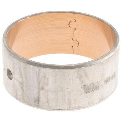
Mahle Clevite Camshaft Bearing for 1998.5-2017 Cummins -SH-1981
$11.29
-
The first commonly used bearing material was an alloy of lead, tin, antimony and arsenic called “Babbitt” which was named after its inventor. Babbitt has physical properties similar to solder. It’s soft which allows it to conform to minor imperfections in geometry and alignment of mating parts. This softness also allows Babbitt to absorb dirt and wear particles that might pass through the bearings clearance space. Babbitt is also very slippery which minimizes friction in the absence of oil during startup.
Although Babbitt is the best bearing material based on its surface behavior, it has one serious shortcoming. By itself, in thick layers, Babbitt cannot carry high loads for long periods. Under the repeated cyclic loading of an internal combustion engine Babbitt will break up and flake out. This reaction to cyclic loading is called “Fatigue.” Bearings are typically constructed with a steel backing to provide support and allow the bearing shells to be an interference fit with their housing.
The earliest insert bearings were Bi-metal construction with a lining of Babbitt. As mentioned above, although Babbitt offered optimum surface behavior, it lacked fatigue strength. It was found however, that the fatigue strength of Babbitt could be significantly improved by reducing its thicknes.
Clevite B-1 Cam Bi-metal “MICRO BABBITT” bearings use a thinner layer of Babbitt lining to provide better fatigue resistance, and Tri-metal bearings which use an extremely thin electroplated overlay layer of Babbitt over a stronger intermediate layer to combine the surface properties of Babbitt with the greater fatigue strength of the intermediate layer. An alloy of Copper, Lead and Tin is the most commonly used intermediate layer.
Original Equipment bearings have employed all of the popular types of materials and construction over the years. Bi-metal Babbitt, Bi-metal Copper- Lead, and Bi-metal Aluminum, have all been used at various times in numerous applications.
Installation of bearings into the block must be done with care to avoid shaving metal off the backs of the bearings. This galling action may cause a build-up of metal between the bearing OD and the housing bore which will result in a reduction in clearance. To prevent galling, check housing bores for a proper 25 to 30 degree lead-in chamfer before installing cam bearings. On blocks without grooves behind the cam bearings, care must be taken to insure that oil holes line up between the bearings and block. Where the block has a groove behind the bearing, the bearing should be installed with the oil hole at the 2 o’clock position when viewed from the front for normal clockwise camshaft rotation. This will introduce oil into the clearance space outside of the loaded area and allow shaft rotation to build an oil film ahead of the load.
Features:
- OE Quality
- Maintains a Factory Performance
| Weight | 1 lbs |
|---|---|
| Dimensions | 1 × 1 × 1 in |
Be the first to review “Mahle Clevite Camshaft Bearing for 1998.5-2017 Cummins -SH-1981” Cancel reply
This site uses Akismet to reduce spam. Learn how your comment data is processed.


Reviews
There are no reviews yet.